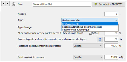
There are three possible modes for controlling ceiling fans:
- Manual
- Automatic with thermostat
- Fully automatic management
These three modes will have an impact on the calculation of degree hours (DH), but also on Cep and Cepn,r values. Now that the Samarat is fitted with a thermostat and can be controlled by a BMS, the two most advanced modes are available for professionals wishing to install ceiling fans. What is the benefit of these regulation methods in the context of the RE2020 calculation? That’s what we propose to clarify in the rest of this article.
Clarify the theory and present calculations
This publication begins by presenting the theoretical framework for the calculations, with a view to clarifying them.
It is completed at the end by a set of simulations that are particularly useful for design offices. For the section on calculations, we have drawn on the work of Maxime Jaymond, head of the New Energie Concept & Carbone design offices.
The simulations measure the impact of justification and regulation methods in regulatory calculations for a typical building in the Mediterranean zone.
Three modes, three performances
In manual mode, the user activates the air fan and adjusts the speed according to his or her feelings. The thermal calculation will then be based on conventional values.
In automatic management mode with thermostat, the thermostat will first trigger the ceiling fan at intermediate flow rate (the calculation engine assumes 60% of the maximum flow rate value).
In fully automatic management mode, the user has no control over the triggering or maximum speed of the ceiling fan. However, in certain configurations, the gain over manual mode is very significant.
As a reminder, in RE2020 the air flow rate is used to determine the value of the air velocity, using the formula: [Air velocity]=0.0032 x [Air flow rate in m3/h / Volume of space mixed in m3].
What is hysteresis?
Hysteresis is a physical phenomenon in which a system does not immediately return to its initial state after a change, even if the cause of the change has been removed.
It results in a delay, a drag or a difference between the change made and the system’s reaction. It is as if the system had a “memory” of what happened before.
Take a magnet and a hairpin, for example. When the magnet is brought close to the hairpin, the hairpin is attracted to the magnet. However, even after moving the magnet away, the hairpin remains magnetised for some time before returning to its unmagnetised state.
In the case of heating controls with thermostats, hysteresis is deliberately introduced into the control so that the start temperature set point is different from the stop temperature set point. This avoids frequent switching on and off of the heating system. For example, the heating can be switched on when the temperature falls below 19.0°C and switched off when it rises above 20°C, creating a hysteresis of 1°C. The temperature is said to be regulated to 19.5 degrees (to within 0.5 degrees).
In the context of ceiling fans, hysteresis illustrates the difference between the measured temperature and the activation of a user reaction (such as a manual action) or an automatic process (such as a thermostat or fully automatic mode), in relation to thermal discomfort.
Don’t be afraid of the basic parameters of hysteresis!
The table below, which explains the calculation of the impact of ceiling fans in RE2020, may seem impressive at first glance, but it is accessible with a few simple explanations.
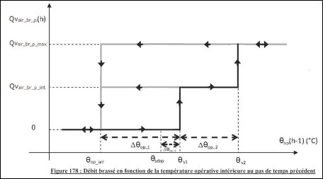
Here are the main concepts that will help you understand this table.
- QVair : débit d’air. air flow. max corresponds to the maximum value; int corresponds to the intermediate value (60% of the maximum)
- θop: operating temperature. It is based on the indoor temperature and the radiant temperature (radiation from the walls).
- θop_arr : operating stop temperature
- θadap: adaptive temperature (to take account of adaptive comfort[i])
- θv1 : operating temperature at intermediate speed
- θv2 : operating temperature at maximum speed
- Δθop1 : difference between the shut-off temperature and the temperature at which the intermediate flow is triggered, without taking adaptive comfort into account
- Δθop2 : difference between the temperature at which the intermediate flow rate is triggered and the temperature at which the maximum flow rate is triggered, without taking account of adaptive comfort
- Δθop3 : difference between the shut-off temperature and the temperature at which the intermediate flow is triggered, taking account of adaptive comfort
The basic parameters of the hysteresis are the last 3 values mentioned above: they express the values for triggering the ceiling fan at intermediate and maximum speed, starting from the set temperature (and for the 3rd, adjusting the set temperature to take account of adaptive comfort). It should be noted that the thermostat is not based on an operating temperature, but only on the temperature of the ambient air (it does not include the radiant temperature). The values to be entered are those provided by the manufacturer, and take into account the characteristics of the thermostat sensor fitted to the ceiling fan. To get an idea of the expected values, in the manual mode calculation, these 3 basic parameters are set to values of 2°C, 4°C and 1°C respectively.
What values does the thermostat version of the Samarat offer?
The three values to be entered in the calculation are :
- Δθop1 : 0°C
- Δθop2 : 2°C
- Δθop3 : 0°C
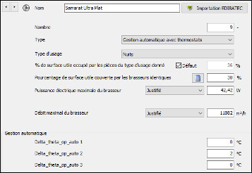
Calculation simulations for an apartment building in zone H3
We have used the same assumptions for the simulations as in our article « Collective housing on the Mediterranean rim: how to comply with the RE2020 constraints? »
The reference building has a surface area of 2,233 m² and comprises 36 flats over two storeys and 2 basement levels. It also includes 1 commercial premises.
Nos actions n’ayant pas d’impact sur le Bbio, nous nous concentrons sur les indicateurs suivants : Cep and Cepn,r hour-degrees (in through and non-through zones).
It should be noted that we did not find any significant difference between the Cep and Cepn,r results. This is why we have grouped the two results in a single column.
The initial scenario is based on a noisy zone (BR2/3) without air conditioning.
1) Impact of justifying values as opposed to simply declaring them
Remember that to be able to enter a justified value, it is necessary to be able to present a measurement resulting from a test in an independent laboratory accredited in accordance with standard NF EN ISO/CEI 17025 by COFRAC or equivalent. The standard tested is NF EN IEC 60879 (air flow and power measurement).
This laboratory test was carried out for Samarat, and is available to design offices.
| Setup | Cep (max 71,7) & Cepn,r (max 71,6) | DH through zone (max 1250) | DH non-through zone (max 1250) |
| Initial: Base with Samarat fan coil units in all bedrooms (night) + all living rooms (day) and reinforced insulation (walls R=4.1; roof R=7.3; ground floor R=4.65 and Uc = 0.8) Fan coil units with a declared flow rate of 11882 m3/h, and power of 42.4W declared | 58,3 | 669,6 | 1130,3 |
| Initial with stirrers with a justified flow rate of 11882 m3/h and a declared power of 42.4W[ii] | 57 (-2%) | 616,7 (-8%) | 1005,7 (-11%) |
| Initial with fans with a declared flow rate of 11882 m3/h, and justified power of 42.4W | 58,1 (0%) | 666,6 (0%) | 1119,4 (-1%) |
| Initial with mixers with a justified flow rate of 11882 m3/h and a justified power rating of 42.4W | 56,7 (-3%) | 613,9 (-8%) | 995,5 (-12%) |
The results show a number of very important points:
- the justification has a considerable impact on DHs, particularly in non-through areas,
- justifying the power has little impact on the Cep value. This is because ceiling fans are energy-efficient, and their influence on energy consumption indicators is marginal.
2) Impact of ceiling fan control mode
The simulations are based on the hysteresis values to be entered mentioned above (Δθop1 : 0°C ; Δθop2 : 2°C et Δθop3 : 0°C) for automatic management with thermostat and fully automatic management. For the fully automatic management mode, the temperature to be used is 26°C. The values always correspond to the Samarat.
| Setu^ | Cep (max 71,7) & Cepn,r (max 71,6) | DH through zone (max 1250) | DH non-through zone (max 1250) |
| Initial: Base with Samarat fan coil units in all bedrooms (night) + all living rooms (day) and reinforced insulation (walls R=4.1; roof R=7.3; ground floor R=4.65 and Uc = 0.8) Fan coil units with a declared flow rate of 11882 m3/h, and power of 42.4W declared | 58,3 | 669,6 | 1130,3 |
| Initial with automatic management with thermostat | 57,3 (-2%) | 584,6 (-13%) | 1006,6 (-11%) |
| Initial with fully automatic management | 57,3 (-2%) | 584,6 (-13%) | 1006,6 (-11%) |
| Initial with automatic management with thermostat + justified flow rate and power | 55,8 (-4%) | 533,2 (-20%) | 886,5 (-22%) |
| Initial with fully automatic management + justified flow rate and power | 55,8 (-4%) | 533,2 (-20%) | 886,5 (-22%) |
Once again, it can be seen that ceiling fans, when allowed to benefit from an improved management mode, will enable a very significant reduction in DH. It should also be noted that as soon as justified performance is combined with an advanced management mode, the gains are considerable, including in terms of Cep and Cepn,r improvement. Finally, we can note that with an equivalent hysteresis configuration, and a temperature of 26°C, the two modes produce the same values. On the project we presented in a previous article, the gain exceeds 20% in DH and 4% in primary energy coefficients. Thermal engineers regularly compete in ingenuity to obtain tenths of Cep points. With this type of configuration, they now have a new string to their bow.
[i] See our article on the subject: « Summer thermal comfort and ceiling fans: can we measure the improvement » : https://www.exhale-fans.com/en/summer-thermal-comfort-and-ceiling-fans-can-we-measure-the-improvement/ [ii] In the table, we show configurations in which the airflow is justified, and the power is simply declared. This approach focuses on the calculation, so that the impact of each of the two quantities can be measured. In practice, laboratory testing to standard NF EN IEC 60879 is used to obtain both values. So, once a test has been carried out, the flow rate and power values are both justified.
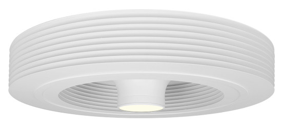
Exhale, the first vortex-effect bladeless ceiling fan
Are you a professional? We have a dedicated area for you.
Find Exhale Fans Europe on Linkedin

